Mechatronic design processes
Micro vs. Macro problem solving
Micro-cycle problem solving
The micro-cycle is a repeatable, foundational process used to tackle individual steps within a larger development project. Originating from systems engineering, it allows developers to flexibly navigate complex tasks by arranging these small cycles in series or nesting them inside one another.
The cycle consists of three main phases:
-
Initiation: The cycle triggers either by analyzing an existing, unclear problem (actual state) or by adopting an externally assigned target (desired state).
-
Synthesis and Analysis (The Core Loop): Developers enter a continuous back-and-forth process. They brainstorm alternative solution variants (synthesis) and immediately evaluate, test, or reject them against the goal (analysis).
-
Resolution: The best alternatives are formally assessed, a final decision is made, and the team plans the next procedural steps or extracts lessons learned.
Practical Example: Designing a Robot's Gripper
Imagine you are engineering a modular mobile manipulator robot (like a "BumbleBee" concept) and you need to design the end-effector (the hand) to pick up a specific object. You would use a micro-cycle to solve this specific sub-problem.
1. Initiation (Procedure based on desired state)
- Adoption of goal: The project requirements state the robot must securely lift a smooth, 150g cubic payload.
- Situation analysis: You calculate that the current arm motors have the torque to lift 150h, but a standard flat, hard-plastic gripper will let a smooth cube slip.
2. Synthesis and Analysis Loop
You bounce between creating ideas and immediately testing their viability:
- Synthesis: "What if we use thick, high-friction rubber pads on the gripper fingers?"
- Analysis: "Calculations show rubber provides enough friction, but it might degrade quickly in an industrial environment."
- Synthesis: "What if we use a pneumatic suction cup instead of mechanical fingers?"
- Analysis: "Suction is great for smooth surfaces, but it requires adding a bulky, heavy air compressor to the mobile base, violating our weight constraints."
- Synthesis: "What if we use a V-shaped mechanical claw with thin silicone gripping strips?"
- Analysis: "The V-shape naturally centers the cylinder, requiring less grip force, and the silicone meets durability and friction needs without needing an air compressor."
3. Resolution
- Analysis and Assessment: You formally compare the rubber pads, the pneumatic suction, and the V-shaped claw against your weight, power, and durability constraints.
- Decision: You officially select the V-shaped mechanical claw with silicone strips as the final design.
- Planning for further procedure: You close this micro-cycle and immediately start a new one to determine the specific PID control loop parameters needed to close the new claw without crushing the payload.
Macro-cycle problem solving (VDI)
How to solve questions?
- Draw VDI
- Define domains (system, mechanical, electrical, software)
- Specify domain-specific design and deliverables
What does VDI mean?
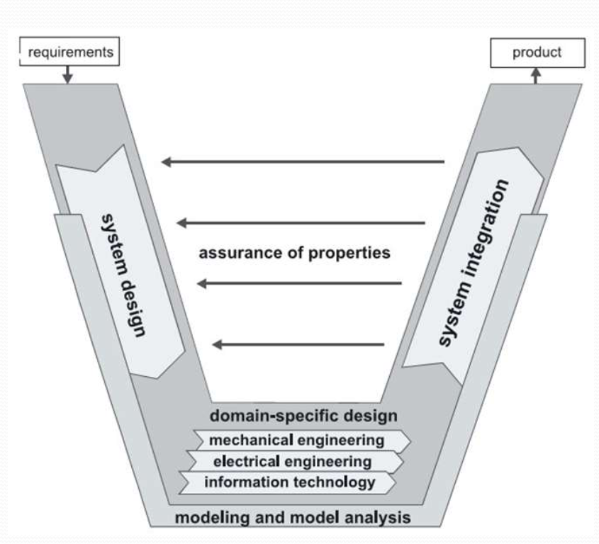
While the micro-cycle is the "engine" used to solve individual, bite-sized problems, the macro-cycle is the iterative overarching roadmap for the entire project, developing complex mechatronic products. Unlike a straight line, it visually represents how design and testing are continuously linked across different engineering disciplines. In German engineering methodology (specifically VDI 2221 for general design and VDI 2206 for mechatronic systems), the macro-cycle dictates the chronological phases a product goes through from an initial idea to a fully documented, ready-to-manufacture system.
You can think of the macro-cycle as the master timeline. Inside every single phase of this macro-cycle, engineers run dozens of micro-cycles to solve the specific problems that arise during that phase.
The classic VDI macro-cycle consists of four main phases:
1. Requirements (Clarification of the Task): Defining exactly what the system needs to do. Gathering requirements, constraints, and constraints to create a strict specifications list.
2. System Design (Conceptual Design): Determining how the system will achieve those requirements in abstract terms. The overall function is broken down into subfunctions, and engineers research and assign working principles to solve them (e.g., choosing between a pneumatic or electric actuator). You establish core functions, brainstorm working principles, and evaluate broad concept variants.
3. Domain-specific Design (Detailed design)
- Turning the abstract concept into a tangible layout. You determine the rough physical form, select materials, size the components, and define the interfaces.
- The project splits into separate disciplines: mechanical engineering, electrical engineering, and information technology (software).
- Each team completes detailed calculations and creates physical, mathematical, or numerical models to simulate their parts before building them.
- Finalizing the exact, final specifications. This includes creating manufacturing blueprints, final 3D CAD models, Bill of Materials (BOM), and exact source code architecture.
4. System Integration (Distributed, Modular, Spatial)
The mechanical parts, custom PCBs, and software code are brought together to form the overall system. Incompatibilities are identified and eliminated. This is where techniques like Software-in-the-Loop (SIL) and Hardware-in-the-Loop (HIL) are used to test real controllers against simulated physics to save time and money.
5. Assurance of Requirements (Verification and Validation
Across the entire "V", the right side constantly checks back against the left side to ensure the actual system matches the desired concept. - Verification: Checking if you built the product right (Does it meet the exact specifications?).
- Validation: Checking if you built the right product (Is it actually suitable for its intended purpose in the real world?).
Software-in-the-loop (SIL) Hardware-in-the-loop (HIL)
Software-in-the-Loop (SIL) and Hardware-in-the-Loop (HIL) are simulation techniques for testing embedded systems. SIL tests compiled code in a virtual environment for early validation. HIL connects real controller hardware to a simulated plant for high-fidelity testing of real-time performance and I/O. SIL focuses on speed and logic, while HIL focuses on timing and physical, real-world interactions.
- **Hardware Presence:** SIL is purely virtual, while HIL involves the physical control hardware (e.g., ECU). - **Purpose:** SIL is used for algorithm development and testing logic early. HIL is used for final verification, fault injection, and testing real-time performance. - **Fidelity:** HIL provides higher fidelity by simulating physical electrical signals, latency, and noise. - **Cost/Time:** SIL is faster and cheaper (no hardware needed). HIL is more expensive and requires mature hardware.When to Use Which:
- Use SIL early in the development cycle to verify software logic, conduct rapid prototyping, and check code functionality.
- Use HIL late in the development cycle for final validation, ensuring the software runs correctly on real hardware and meets timing requirements
TRIZ
How to solve questions?
- Choose two contradicting features (performance requirements) in your system (e.g. weight vs. speed)
- Find the TRIZ principles used for resolving the conflict (improving one feature without worsening the other) using the contradiction matrix
- You can also generally use TRIZ principles for brainstorming
What TRIZ even means?
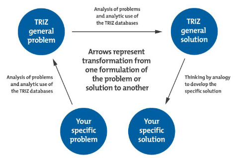
TRIZ (Theory of Inventive Problem Solving) is a systematic, logic-based approach to engineering and innovation. Instead of relying on random brainstorming, TRIZ is based on the analysis of thousands of patents to identify universal patterns of invention.
The core philosophy of TRIZ is that true innovation requires identifying and eliminating contradictions rather than accepting compromises or trade-offs.
The TRIZ process relies on a few key tools:
- 39 Engineering Parameters: A standard list of physical characteristics (e.g., weight, speed, reliability) used to define the problem.
- The Contradiction: The core issue where improving one parameter causes another to deteriorate.
- The Contradiction Matrix: A lookup table where you intersect the parameter you want to improve with the parameter that is getting worse.
- 40 Inventive Principles: The matrix outputs specific, standardized principles (e.g., "Segmentation," "Preliminary Action," "Asymmetry") that have historically solved that exact type of contradiction.
Applying TRIZ to the FDM 3D Printing Problem
The goal is to increase printing speed without sacrificing dimensional accuracy or surface quality due to vibrations and flow errors. Here is how we break it down using TRIZ.
a. The Contradiction
- "If we improve the printing speed, then the dimensional accuracy and surface quality get worse due to vibration and flow errors."
b. Selecting TRIZ Engineering Parameters We need to map our specific problem to the standard 39 TRIZ parameters:
- Parameter to be improved: Parameter #9 (Speed) or Parameter #39 (Productivity).
- Parameter that worsens: Parameter #29 (Manufacturing precision) or Parameter #13 (Stability of the object's composition).
c. Identifying Inventive Principles Using the TRIZ Contradiction Matrix, looking up the intersection of improving Speed (#9) while worsening Manufacturing Precision (#29) yields several standard inventive principles. We will select four highly relevant ones:
- Principle 1: Segmentation (Divide an object into independent parts).
- Principle 10: Preliminary Action (Perform required changes to an object completely or partially in advance).
- Principle 15: Dynamics (Allow the characteristics of an object or environment to change to be optimal).
- Principle 28: Mechanics Substitution (Replace a mechanical system with a sensory or active field).
d. Concept-Level Design Ideas Using those principles, here are proposed solutions to resolve the contradiction:
-
Idea 1: Input Shaping (Applies Principle 10: Preliminary Action & Principle 28: Mechanics Substitution)
- How it works: Instead of trying to build an infinitely rigid, heavy frame to resist vibration (which limits speed), we substitute mechanics with advanced control systems. By using an accelerometer to measure the printer's natural resonant frequencies, the software pre-calculates and alters the motor commands in advance (preliminary action). The firmware injects opposing frequencies into the motion trajectory, actively canceling out vibrations before they translate to the print.
-
Idea 2: CoreXY Motion Architecture (Applies Principle 1: Segmentation & Principle 15: Dynamics)
- How it works: Traditional "bed-slinger" printers move a heavy glass bed on the Y-axis. At high speeds, this massive moving inertia destroys precision. We segment the motion system: the heavy bed only moves slowly downward (Z-axis), while the lightweight print head handles all rapid X and Y movements dynamically at the top of the frame.
- Idea 3: Pressure Advance / Linear Advance (Applies Principle 10: Preliminary Action)
- How it works: At high speeds, molten plastic acts like a spring inside the nozzle, leading to flow errors (bulging corners and under-extrusion on straights). Pressure Advance is a control process that calculates the required extrusion pressure beforehand. It commands the extruder motor to push extra filament right as the toolhead accelerates, and retract slightly as it decelerates, ensuring perfect flow accuracy regardless of speed.